The Inner Workings of the Moog Multimode Filter
Editor’s Note: This article was originally featured in a previous edition of our WebZine. We're running it again because of the ongoing relevance of the information, the availability of the award-winning Moog Multimode Filter, and its inclusion in the newly introduced, money-saving Electronic Music Bundle at the UA Online Store.
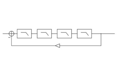
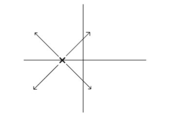
The Moog four-pole resonant filter is a classic design with a distinctive, characteristic sound. Structurally, the filter is formed by placing four identical one-pole filters in cascade (see Figure 1) and creating a feedback loop around them. As the amount of feedback is increased from zero, the (initially coincident) closed-loop poles of the system diverge, with two poles becoming increasingly resonant. If the four filters are normalized to have a DC gain of unity, the closed-loop system becomes unstable for feedback gains exceeding four. Figure 2 shows the trajectory of the system’s poles as feedback is increased.
When the system becomes unstable, oscillation will result. Theoretically, the system could maintain a sinusoidal oscillation indefinitely at constant amplitude with the feedback gain set to exactly four, as the system would be marginally stable. In practice, to produce oscillation, feedback gain is increased beyond four, so that the system is strictly unstable, and the oscillation grows until it reaches a point of saturation, or maximum amplitude. Because of the filter’s instability, saturation is necessary to prevent the amplitude of oscillation from growing in an unbounded manner. The saturated output will not be a pure sinusoid, but will contain energy at harmonics of the frequency of oscillation, due to the saturation. In order to implement the Moog structure, four one-pole filters must be connected in a feedback configuration.
The Moog filter was designed to vary the filter’s cutoff frequency over time. Typically the variation is controlled by an LFO (low-frequency oscillator) or an envelope follower, which tracks the amplitude of the input signal. The filter itself thus has two controls: cutoff frequency, which sets the frequency of the four one-pole filters within the feedback loop; and resonance, which sets the amount of feedback in the loop and determines the resonance of the filter.
There are several features of the Moog filter that make implementation as a discrete-time system nontrivial. First, there is a feedback loop containing both a nonlinearity and a series of filters. Second, there is a delay-free path around the feedback loop. Finally, the filters within the loop must have cutoff frequencies that can be adjusted without artifact as a function of time.
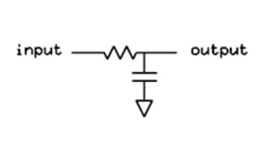
Figure 3 shows a passive analog one-pole filter circuit. The filter’s state is determined by the voltage on the capacitor C. This voltage is also equal to the filter’s output. The filter’s cutoff frequency can be adjusted by changing the value of the resistor R. Notice that changing the value of R does not, however, change the amount of energy stored in the filter’s capacitor. Neither does it instantaneously change the value of the filter’s output.
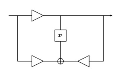
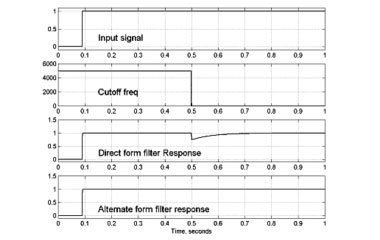
A direct-form implementation of a discrete-time one-pole filter is shown in Figure 4. With appropriate coefficients, this structure can be used to model the filter shown in Figure 3. As long as the cutoff frequency of the filter is fixed, the discrete-time filter can be made to closely approximate the behavior of the analog filter at frequencies well below the Nyquist limit. However, it can be shown that when the cutoff frequency of the filter is changed, the change in filter coefficients results in a discontinuity at the filter’s output. This discontinuity is an artifact of the discrete-time implementation of the filter. If the cutoff frequency of the filter is continuously varied, a continuous stream of artifacts will appear at the filter’s output. By limiting the rate at which the filter’s coefficients can change, these artifacts can be reduced, but not eliminated.
For the UA Moog Multimode Filter, a non-standard filter structure was implemented by explicitly modeling the state of the capacitor in the filter illustrated in Figure 3. The alternate structure allows the filter’s coefficients to be changed arbitrarily, at arbitrary rates, without introducing artifacts into the filter’s output. The physical energy represented by the discrete-time filter’s state is thus independent of the filter’s coefficients. Figure 5 shows the outputs for the direct-form filter and the alternate-form filter with a DC input applied, as the cutoff frequency of the filter is varied. As can be seen, the output of the direct-form filter contains artifacts due to the changing cutoff frequency, while the output of the alternate-form filter does not.
In order to implement the Moog structure, four one-pole filters must be connected in a feedback configuration. As an analog circuit design, this can be accomplished by adding a portion of the filters’ output to the input signal. Direct translation to the discrete-time domain is not trivial. Conventional calculation of the filters’ output leads to a one-sample delay incurred when the signal is combined with the input signal. This delay drastically affects the behavior of the feedback loop. Typically, if a linear system contains feedback, the closed-loop transfer function of the system can be computed, and the discrete-time system can be implemented directly, based on the calculated transfer function. However, if there is a nonlinearity present within the feedback loop, this technique cannot be carried out. For the case of the UA Moog filter, the technique would not work even in the absence of nonlinearities, because correct time-varying behavior of the filters depends on the structure developed in the previous section. Thus, the one-pole filters within the feedback loop must be implemented directly.
As mentioned earlier, "stable" self-oscillation of the filter depends on the fact that some element of the structure saturates, or "clips." This requires inclusion of some form of nonlinearity within the filter’s feedback loop. Because of the presence of this nonlinearity, and because of the special one-pole filter structures used, pre-calculation of closed-loop behavior could not be carried out, and the filter had to be implemented directly as a feedback structure. Special techniques were developed to implement this feedback structure without incurring the one sample of delay usually encountered.
By implementing the feedback structure directly, the saturation of the filter could be implemented in an integral way. This allowed the filter to self-oscillate with a stable amplitude of oscillation. However, inclusion of the saturating element within the feedback loop leads to a potential problem. Because the signal re-circulates indefinitely within the feedback loop, any non-linearities present within the loop can potentially increase the bandwidth of the signal in an unbounded way. Unless the bandwidth of the signal is bounded, there is no way to eliminate aliasing in a discrete-time system. Inclusion of an anti-aliasing filter within the feedback loop could solve the problem. However, if the filter were to be placed within the feedback loop, a zero-phase response would be necessary to prevent disturbing the action of the feedback. Therefore, care had to be taken to implement the feedback loop in such a way that the bandwidth of the re-circulated signal could be constrained.
We were able to solve all the above problems through various signal-processing techniques. The result is a discrete-time structure that approximates the behavior of the Moog resonant filter, without the common artifacts displayed by many discrete-time systems.
For an excellent treatment of the Moog filter, root locus techniques and other topics, see my fellow UA DSP engineer Tim Stilson's Ph.D. thesis, "Efficiently-Variable Non-Oversampled Algorithms in Virtual-Analog Music Synthesis," which is available for downloading.
— Dr. David Berners
Read More
Passion Pit’s Michael Angelakos on Apollo, UAD & Creativity
Passion Pit frontman Michael Angelakos breaks down the group’s creative process and how Apollo and UAD plug-ins act as a main ingredient.
Set Up Unison Technology
with your Audio Interface
Everything you wanted to know about UA's Unison™ technology but were afraid to ask.
Exploring Apollo’s Realtime Analog Classics
Watch producer/drummer Joey Waronker as he tracks The New Pornographers' A.C. Newman with Apollo interfaces and its included Realtime Analog Classics Bundle.


