UA's Art and Science of Modeling UAD Plug-Ins, Part 2
In our last installment, we gave you a glimpse into the history of the Putnam legacy and Universal Audio’s special relationship with Stanford University’s Center for Computer Research in Music and Acoustics (CCRMA). Read on to get deep with UA’s Chief Scientist and Consulting Professor at CCRMA, Dr. Dave Berners, and Software Product Manager Will Shanks about the mathematical processes and methods used to create Universal Audio’s industry-leading plug-ins, renowned for imparting the same rich vintage warmth of the analog hardware they emulate.
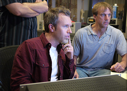
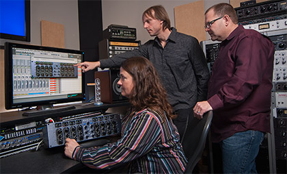
Professor at Stanford University's CCRMA, Dr. Dave Berners, engrossed
in the latest UAD Powered Plug-In development project.
True Physical Circuit Modeling
Unlike other plug-in makers, Universal Audio constructs their software using circuit modeling, rather than circuit simulation. With circuit simulation, a number of test signals are simply run through the unit being modeled, and a mathematical model is then developed to mimic these changes. UA prefers to follow the more rigorous scientific approach of circuit modeling by fully rebuilding all elements of each circuit — whether transistor, transformer, or tube — in the digital world. The results are the best-sounding and most faithful emulations of the subtle nuances of classic analog hardware available.
In order to do true physical modeling of analog hardware, UA engineers usually have to discover their own methods, instead of relying on premade software to get the job done. “Securing useable DSP code directly from off-the-shelf circuit modeling software would be difficult,” explains Dr. Dave Berners, UA’s Chief Scientist and in-house design guru. “For example, the SPICE (Simulation Program with Integrated Circuit Emphasis) program provides simulated outputs for a given circuit, but does not use models that are appropriate for fixed-interval sampled systems. Some of the standard models for non-linear components within the SPICE program are not elaborate enough for our purposes. Signal modeling is fine for linear systems, but inadequate for non-linear systems. For equipment with unknown non-linearities, such as vintage analog compressors, a full characterization cannot be made with a finite number of test signals.”
The unique characteristics and quirks of vintage analog gear can also be lost when using circuit simulation. “Many important system behaviors cannot be predicted from the schematics because parasitic effects are not recorded on the schematics,” Dave offers. “Coupling between inductors, stray capacitances, and equivalent series resistances are usually not entered on circuit drawings. However, SPICE is great for quick experimentation along these lines, provided that someone knows likely places to add the parasitic effects.”
The Mathematical Methods Behind UA’s Circuit Modeling
At the heart of the modeling process is determining how an audio signal will be affected within the frequency and time domains as it passes to the output. According to Dr. Dave Berners, “Our strategy is a sequence of first developing a model for the ‘easier’ parts of the circuit, and then moving on to its non-linear sections. Any circuit sections considered linear over the expected operating range are easy to fully characterize, so we do those first. For the non-linear or time-varying sections, we construct the appropriate non-linear differential equations, and then figure out how to solve them with adequate accuracy for a reasonable computational cost. There cannot be a ‘method’ to determine the best modeling process, mainly because there are too many dimensions that need to be considered.
with one mission — to deliver the most authentic emulations of the
subtle nuances of classic analog hardware available.
“Usually, there are multiple ways to model a system, but it is not always easy to predict the efficiency — accuracy versus cost — of each model. As far as securing a unique solution, we can get arbitrarily close to the desired solution, unless the original system is chaotic. Some unstable systems, such as the Moog® Multimode Filter Plug-In, could be considered chaotic — meaning that they are extremely sensitive to initial conditions or noise-like processes — but we can still check that we are securing solutions that are statistically accurate.”
“In terms of the construction of a plug-in algorithm,” Berners continues, “the process involves two complementary steps. This first step is to produce a possibly non-linear differential equation that describes the behavior of the system to be modeled. We first have to understand the behavior of all subsystems and components — including optical, magnetic, electrical, and mechanical elements. This initial differential equation describes a system in terms of a finite number of states. The system behavior is modeled by specifying how each state will change as a function of all of the values and their derivatives. Hopefully, the finite number of states in the equation will be relatively small.
“For linear electrical components, there would be one state for each reactive component: inductor or capacitor. Resistive or loss components do not increase the order of a system. When dealing with non-linear components, it can be difficult to reduce the order to something manageable. A transformer’s magnetic core, for example, can have a very large number of magnetic domains that influence its behavior. So, by means of some statistical methods, we reduce the number of states for our transformer model to several thousand. For acoustic spaces, such as reverberators, these ‘states’ may represent the acoustic pressure at every point within the volume of a room. This can be reduced to a finite, but still pretty large, number of points in space.
“The second step involves carrying the initial differential equation into the discrete-time universe, which means that we need to find a numerical method to approximate its solution. As mentioned already, we can either solve the ‘exact’ equation approximately, or find an ‘approximate’ equation that has known exact solutions.”
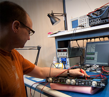
modeled in order to capture the unique personality of its
hardware counterpart.
Depending upon the nature of the system being modeled, either Step 1 or Step 2 will be more difficult, Berners explains. “For spatially distributed systems, especially systems with magnetic, acoustic, or optical elements, it may be very difficult to produce a relatively low-order model for the system. For highly non-linear systems with feedback and high bandwidth, Step 2 could become very difficult.”
In terms of design methodology, once Dr. Berners and his design team have separated the linear time-invariant sections, they cannot look at any remaining elements separately. Why? “Because subsystems that interact in a non-linear way cannot be solved separately,” he explains. “Instead, we must find a simultaneous solution. It’s a complex, time-intensive process, but one that results in a highly realistic-sounding modeled plug-in.”
Although Universal Audio employs some of the world’s most talented circuit-design engineers and programmers, there are times when the modeling process hits a roadblock. “Difficulties can arise either in constructing the model or in implementing that model,” Dave concedes. “Examples of ‘difficult’ models would be the El-Op [the critical electro-optical gain-change cell] in the Teletronix® LA-2A Classic Leveling Amplifier Plug-In, or the transformer in the [Empirical Labs EL7] FATSO Jr/Sr. Tape Simulator and Compressor Plug-In. Examples of ‘difficult’ implementations would be the 1176 Classic Limiter Collection’s feedback loop, the Moog Multimode Filter, or the SPL Transient Designer plug-ins. All of these plug-ins required special techniques to make the discrete-time systems behave accurately.”
There is another class of difficulty that while not fundamentally difficult involves a level of complexity that can become a black hole of time and resources. “The EQ section for the SSL E Series Channel Strip Plug-In would be an example where we had to perform page after page of messy analysis to secure the results we wanted,” says Dr. Berners. “But that was more of a ‘grind it out’ problem, rather than a fundamental obstacle. But we always persevere and get the results we target.”
The Evaluation Phase
After the UA engineering team develops the series of differential equations and mathematical transfer functions that define the unique behavior of the hardware being modeled, the resultant DSP code is then evaluated by product management. It’s in this stage that expert ears become an invaluable resource, as the software team works to have the plug-in sound and behave exactly like its hardware counterpart.
“Listening tests are a great way to expose software bugs,” Dr. Berners explains. “It’s a very quick way to determine what causes a listening difference. Rarely do we to have to ask ourselves, ‘Gee, I wonder why it sounds like that?’ Sometimes electrical component mistunings will be noticed in the listening phase. Every once in a while, some important parasitic behavior in a circuit will escape detection until the listening tests and will have to be added.”
of involving the experts and original equipment manufacturers such
as Moog, Manley Labs, EMT, and Empirical Labs,
has made for better products.”
Working closely during the plug-in evaluation process with Dr. Dave Berners is UA’s Software Product Manager, Will Shanks, who rigorously tests the in-development code from every angle. “Since for each project I’ve already specified along with the designer what the most important sonic attributes are from early study of the device, I know already know the most important behavioral details to focus on.
“From the very beginning, I will set up the emulation evaluation plug-in side-by-side with the target hardware device,” explains Shanks. “In general, I first perform ‘ad-hoc’ listening determine whether the plug-in captures the general ‘vibe’ of the hardware.
“I typically start at the far ends of any control range, since they tend to have the most extreme behavior and can easily reveal potential discrepancies between the target device and the model. It is usually necessary anyway, since the tapers of the user controls may not be implemented on the first pass of a model, but the range ends are almost always represented.
“We use both test tones and program material during these evaluation phases,” says Shanks. “The test signals used tend to differ depending on the hardware we model. Sweeps, tones and noise bursts, steady-state tones, and single samples serve different purposes for different processors. Similarly, various solo instruments, full mixes, or whole multitrack sessions may come into play; some may be more useful than others for a given product. Over the years I have gathered trusted sound sources that I know intimately and that tend to quickly expose problems or inaccuracies in a model. I intuitively reach for the right files that have specific sonic characteristics to help ‘put the microscope’ on an attribute in a given product. If I do find a sonic discrepancy in the basic implementation, it is more often than not a bug.
“At the second revision, those obvious bugs and discrepancies might be addressed, but there may be more nuanced details that may remain, or one fix may uncover some other issue. Sometimes it’s like peeling an onion, and like working on a mix, the answer might not be immediately obvious in communicating the problem. I am looking a little deeper at this stage, getting a little more picky, and sharing my observations in real time with the designer in the studio.
“If I do find a sonic discrepancy at this stage, it is more often than not a bug, but sometimes I may inadvertently find an unexposed behavior that may have been missed that contributes to the overall sound — it might be secondary or even tertiary to the known nonlinearites. Sometimes in these cases, we’ve benefitted from the collaboration with our licensing partners or other experts on a given device. ‘Oh, that? You can hear that? Yes, well we know about that…’ they sometimes say. The complexity of the target device and model usually dictates the number of iterations we may go through.”
EveAnna Manley of Manley Labs during development of the
UAD Manley(R) Massive Passive EQ Plug-In.
This back and forth revision process reveals fundamental differences in how engineers like Dr. Dave Berners and product managers like Will Shanks describe and view the characteristics of a plug-in emulation. “Often there’s an effort of ‘statement translation’ that needs to happen between me and the plug-in designer,” says Shanks. “I have an audio engineering background rather than electrical engineering. Sometimes if I get the sense that something is missing in part of a model, but I’m not totally sure where the discrepancy is coming from, the engineer has to translate my observation in order to look at some element of the model versus the hardware response I’m focusing on. Luckily, we’ve come to understand each other’s language over the years, and show and tell always helps. It’s actually one of my favorite parts of the process.”
Depending on the project, the product manager’s job may be much more than basic definition and sonic sign-off. “Usually with an emulation, the parameter set and behaviors largely define themselves. In rare cases it is my job to ‘voice’ or characterize by ear certain elements of a plug-in. For example, with the case of the late field for the EMT 140 Plate Reverb Plug-In, that took me four months.
“Another example might be the reimagined Cooper Time Cube MkII. In these ‘digital only’ cases, the design is much more hands on for the product manager. This is also true for non-emulations like with the Precision Series of UAD tools. In some of these ‘digital only’ cases I might be creatively tuning the sonic behaviors, or with the input of outside listeners."
Not only does UA work in teams internally to make sure that the resulting plug-ins sound as close as possible to vintage analog hardware they model, but there is often close collaboration with the companies that made the original hardware and with expert customers who are familiar with the original hardware.
“Most importantly, Dave and his algorithm team are without a doubt doing the best work on the face of the planet in this unique discipline. But the secondary benefit is that we can collaboratively evaluate the plug-ins to get them as close as possible to the hardware," says Shanks. "I’m convinced that our approach of involving the experts and original equipment manufacturers such as Moog, Manley Labs, EMT, and Empirical Labs, has made for better products.”
— James Douglas
Read More
Set Up Unison Technology
with your Audio Interface
Everything you wanted to know about UA's Unison™ technology but were afraid to ask.
Exploring Apollo’s Realtime Analog Classics
Watch producer/drummer Joey Waronker as he tracks The New Pornographers' A.C. Newman with Apollo interfaces and its included Realtime Analog Classics Bundle.
Creating a Multi‑Unit Apollo Setup
In this video, watch producer/engineer Fab Dupont (Jennifer Lopez, Mark Ronson) install a multi-unit Apollo system and show you how to easily set it up with your DAW and record with UAD plug-ins in Console 2.0. Featuring the band DEDE.


